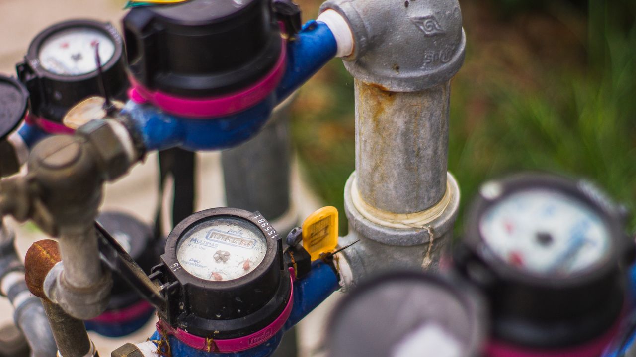
Water meters and gas meters are often installed in locations that are hostile to wireless communication: underground meter pits, subsurface vaults, and curb boxes that are sealed for weatherproofing. These environments combine the signal attenuation of soil and concrete with physical constraints on antenna placement and size. Understanding how LoRa signals actually behave in these conditions — not how they perform in free space or in idealized scenarios — is what separates an antenna selection that works in the field from one that works in the lab and fails during deployment.
What soil does to 868 MHz and 915 MHz signals
LoRa smart metering deployments in Europe primarily use 868 MHz; North American deployments use 915 MHz. These frequencies have different propagation characteristics, but both are significantly attenuated by soil. The attenuation rate depends on the soil composition, moisture content, and compaction.
Dry, sandy soil attenuates RF signals at around 0.1–0.3 dB per centimeter. Clay-heavy soil, which retains more moisture, attenuates more strongly — 0.5–1.5 dB per centimeter is a commonly measured range. Saturated soil — after rain, in areas with high water tables — attenuates even more, potentially 2–3 dB per centimeter.
A meter installed 30 cm below grade in moderately wet clay soil faces a path loss of 15–45 dB before the signal has even reached the soil surface. This is on top of the free-space path loss to the gateway. The link budget for underground meter installations must explicitly account for this burial attenuation, not treat it as a marginal factor.
Concrete and cast iron: what’s between the meter and the sky
Water meter pits and vaults are typically constructed from concrete or masonry, with a cast iron or composite access cover at grade level. Each of these materials has its own attenuation characteristic. Reinforced concrete attenuates LoRa-band signals by 10–20 dB per 10 cm of thickness, depending on the reinforcement density. A 15 cm concrete vault wall introduces 15–30 dB of additional attenuation on top of whatever the soil and cover contribute.
Cast iron manhole covers are essentially opaque to RF signals at LoRa frequencies. A meter antenna positioned directly below a cast iron cover faces a near-complete signal block in that direction. Composite covers — glass fiber reinforced polymer — are significantly more transparent, with attenuation typically below 5 dB. The material of the access cover is therefore a first-order variable in underground meter antenna performance, not a secondary consideration.
Antenna positioning within the meter pit
Within the constraints of the meter pit geometry, antenna positioning substantially affects link performance. An antenna oriented vertically, with its high-gain plane pointed horizontally, radiates signal in a toroidal pattern — maximizing signal toward the walls and cover of the pit rather than upward toward the gateway.
An antenna oriented horizontally — lying on its side relative to the axis pointing toward the gateway — has its high-gain plane directed upward, which is the useful direction for reaching a gateway mounted above grade. The practical constraint is that many meter installations have fixed antenna orientations determined by the meter electronics housing, with limited ability to adjust the antenna geometry for the specific installation.
Where the meter design permits antenna repositioning, testing actual received signal strength at the gateway with the antenna in different orientations identifies the best configuration for each specific meter pit geometry. The difference between the best and worst antenna orientations in a confined metallic space can be 10 dB or more — a factor that determines whether a marginal installation works or fails.
Smart Metering Antennas with external placement options
Some smart metering systems address the underground signal challenge by separating the antenna from the meter electronics. A magnetic mount or adhesive mount external antenna, with a cable running from the meter electronics to the antenna, allows the antenna to be positioned at the grade level access point — mounted on the inside surface of a composite cover, or in the neck of the meter pit where attenuation is lower — while the meter electronics remain at the installation depth.
This approach introduces cable length considerations: the coaxial cable run from the meter to the external antenna has its own insertion loss, typically 0.5–2 dB per meter depending on the cable specification. For a 50 cm cable run, this is a minor factor. For longer runs, it accumulates and must be included in the link budget.
The more significant benefit of external antenna placement is not just the reduction in burial attenuation — it’s the ability to use a larger antenna that would not fit within the meter housing. A larger antenna has higher gain and improved radiation efficiency, which provides link margin that offsets the remaining burial losses.
Gateway density and link budget planning
The engineering response to high burial attenuation in smart metering is typically a combination of higher-gain gateway antennas, elevated gateway mounting heights, and reduced gateway spacing compared to surface-level IoT deployments. A gateway network designed around surface-level device performance will have insufficient link margin for underground meters unless the burial attenuation has been explicitly included in the coverage planning.
Field measurements from representative meter pit installations — with actual signal level readings at several candidate gateway positions — are more reliable than coverage simulations for underground deployments, because the soil and structure variables that drive actual attenuation are difficult to model accurately without site-specific data. Deploying a small pilot network, measuring what actually happens, and adjusting gateway placement based on measured data is a more reliable path to a working network than refining simulation parameters.